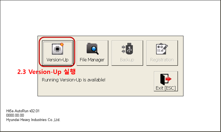
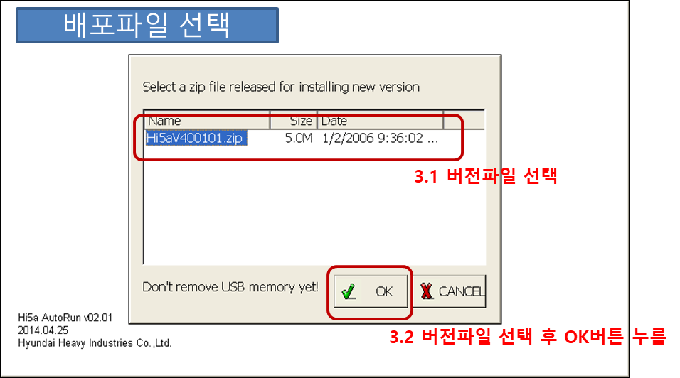
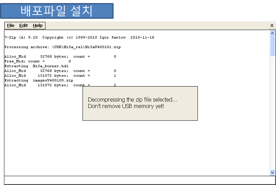
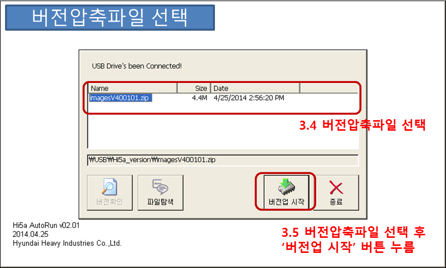
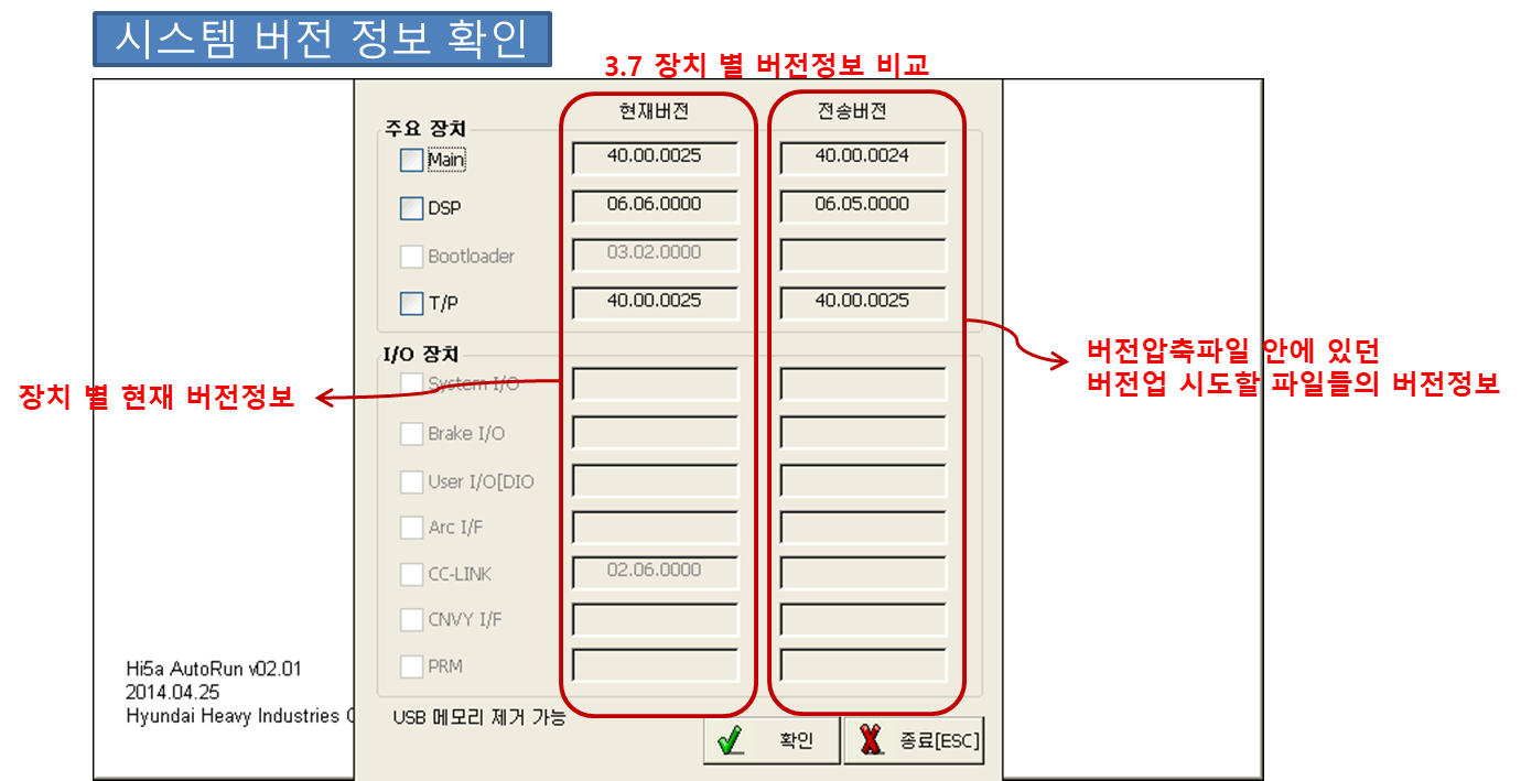
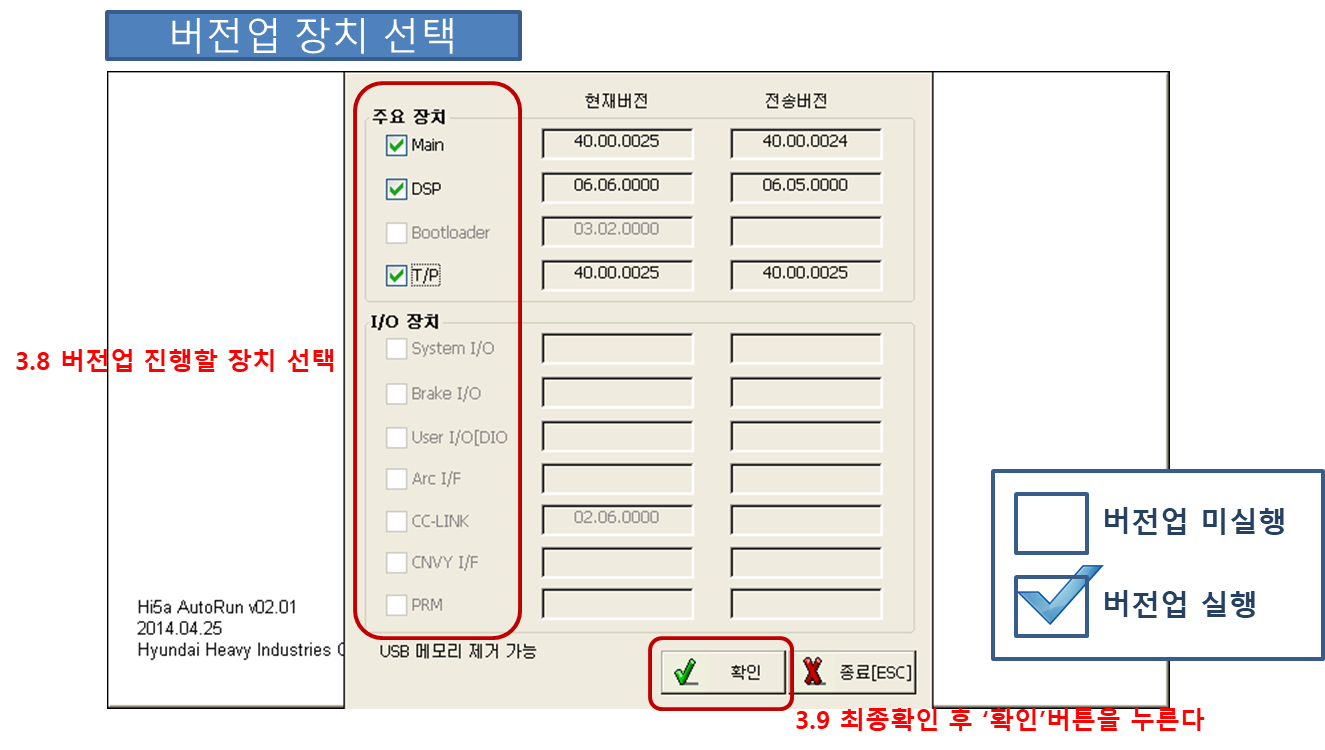
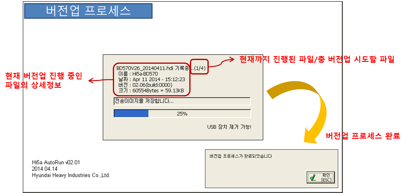
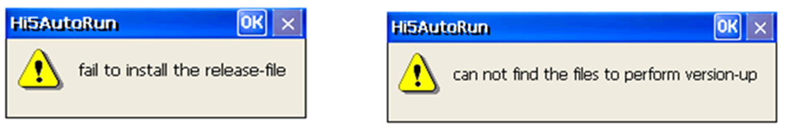
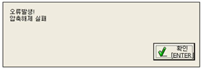
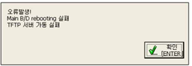
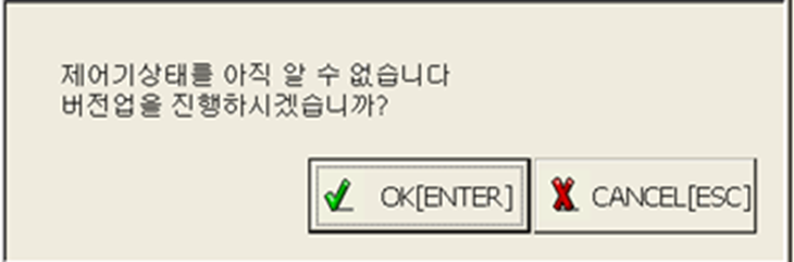
- How to upgrade Hi5a controller version
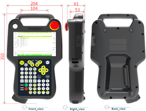
- Separate use of TP520, TP530 SW
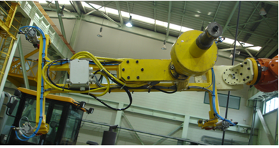
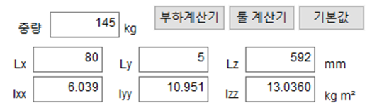
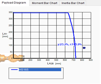
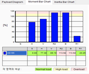
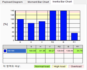
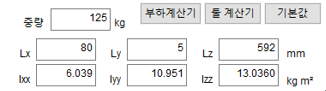
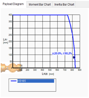
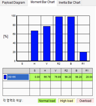
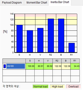
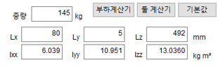
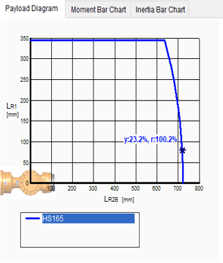
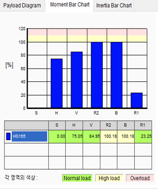
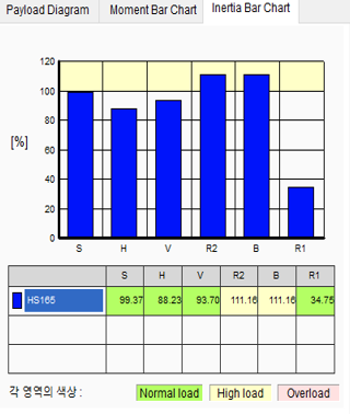
- Understanding robot payload
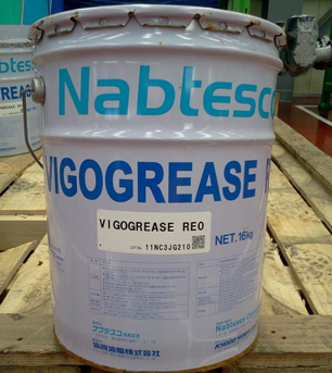
- Notice on prohibition of mixing reducer grease (VIGO + EUREKA)
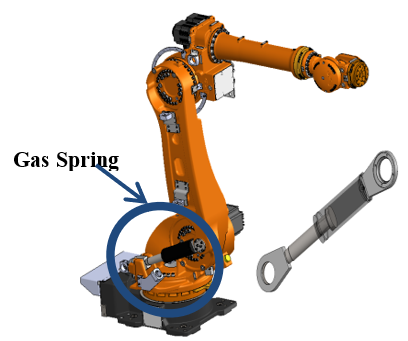
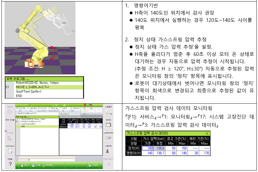
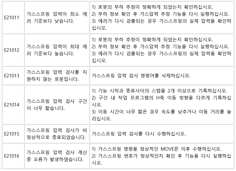
- Gas spring management (monitoring)
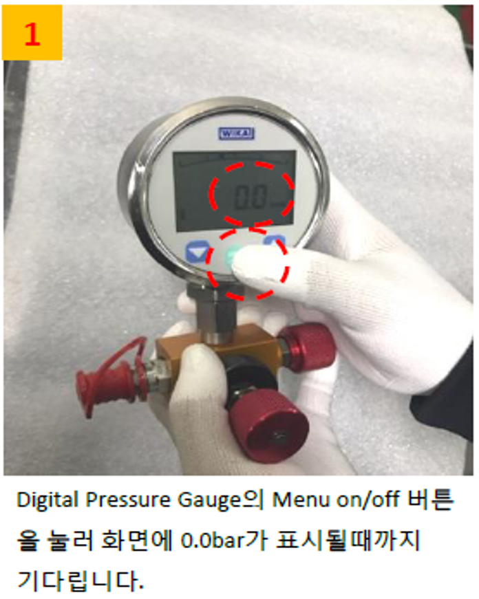
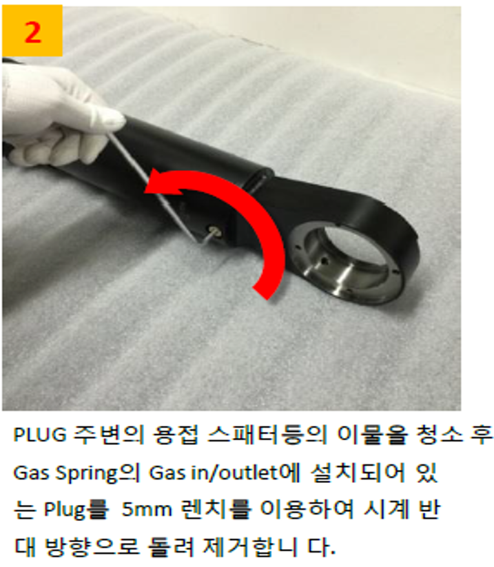
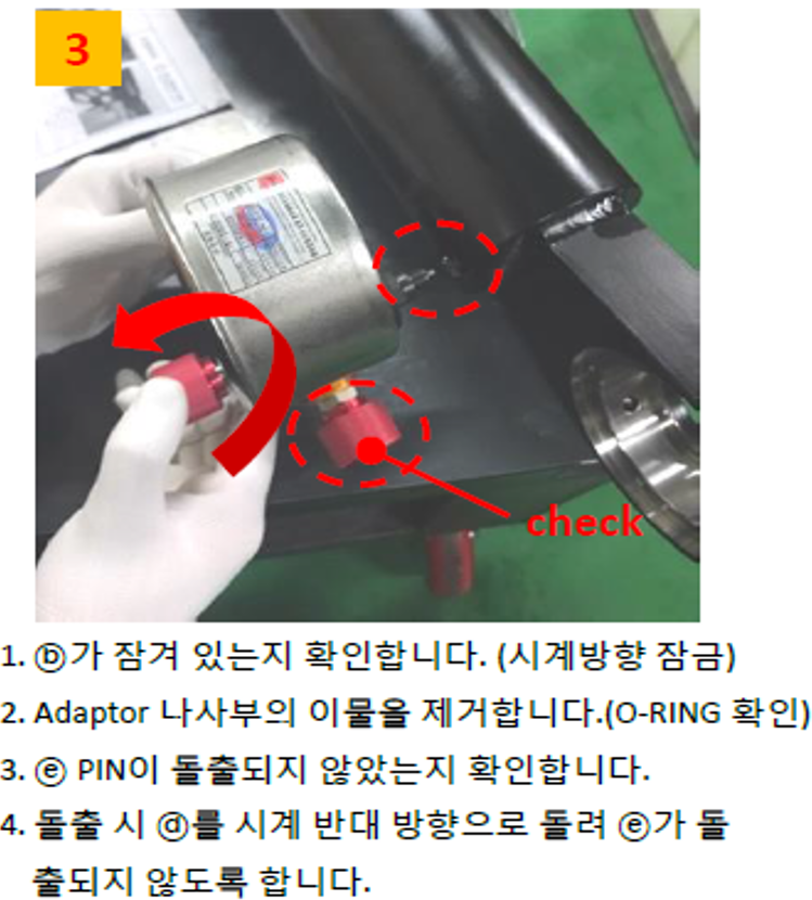
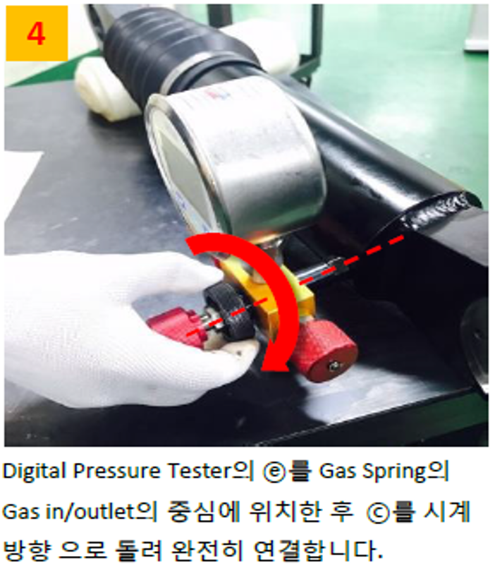
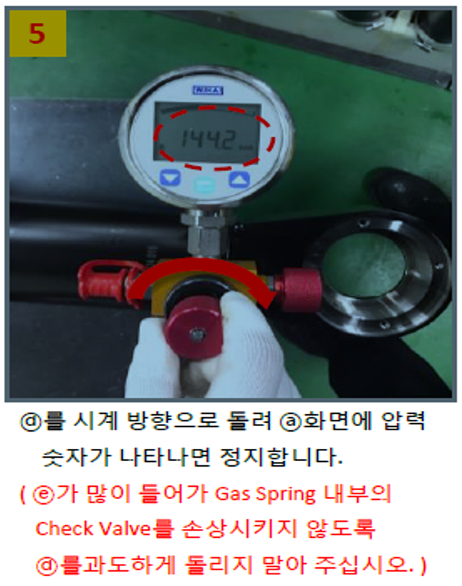
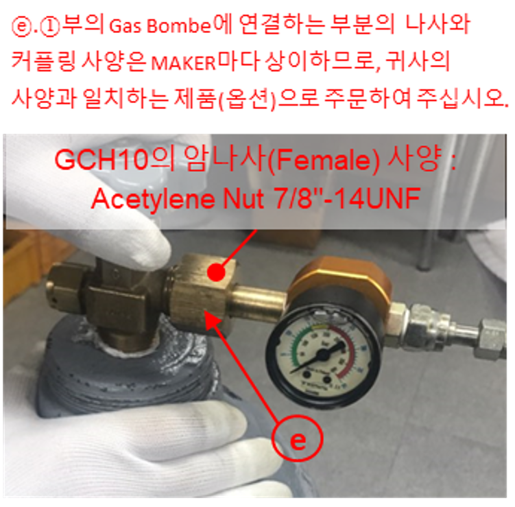
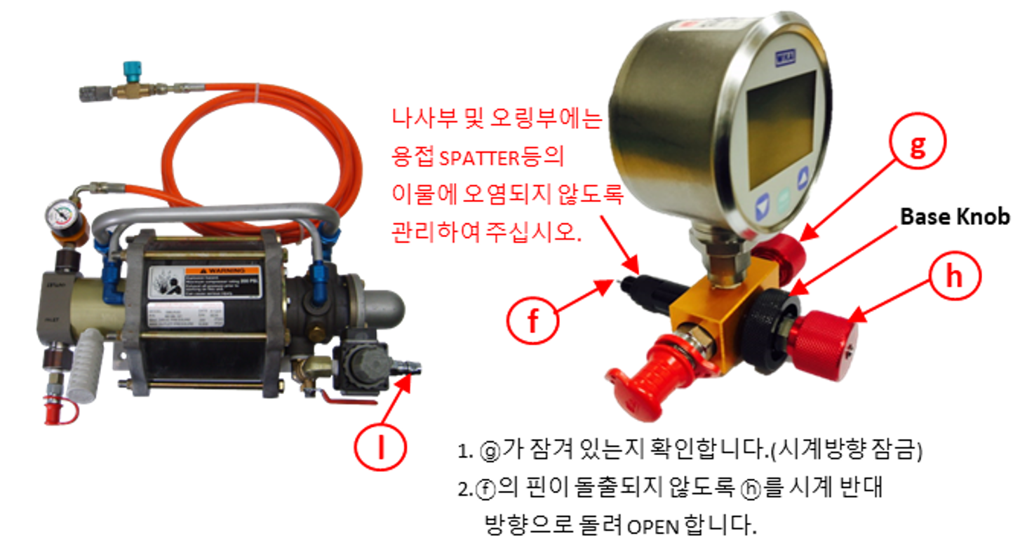
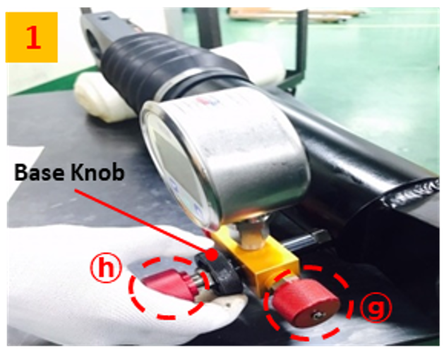
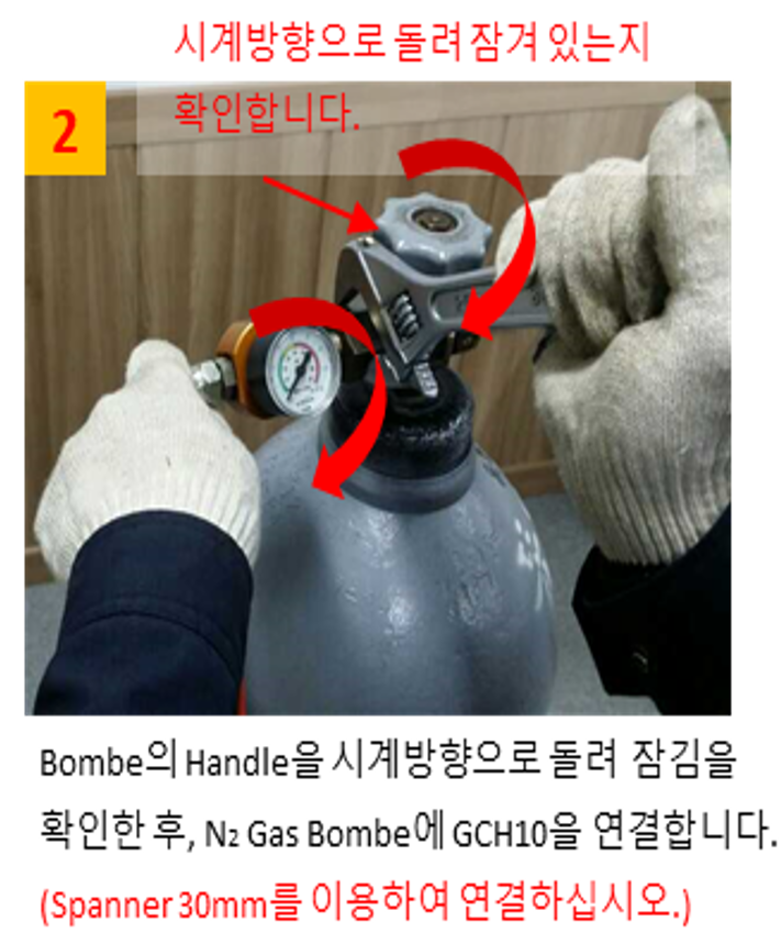
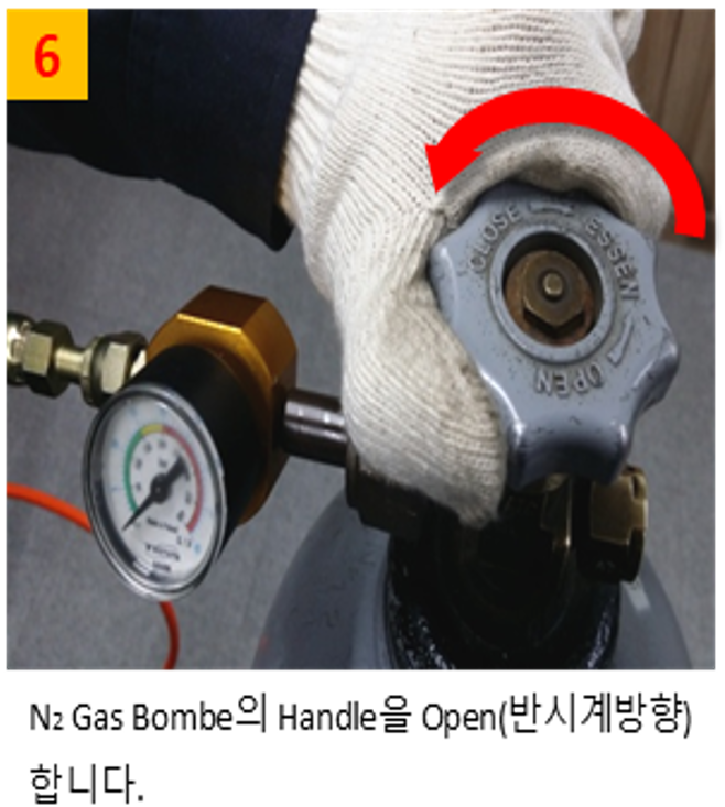
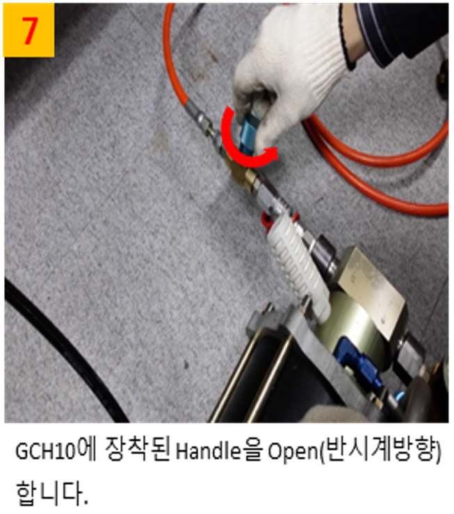
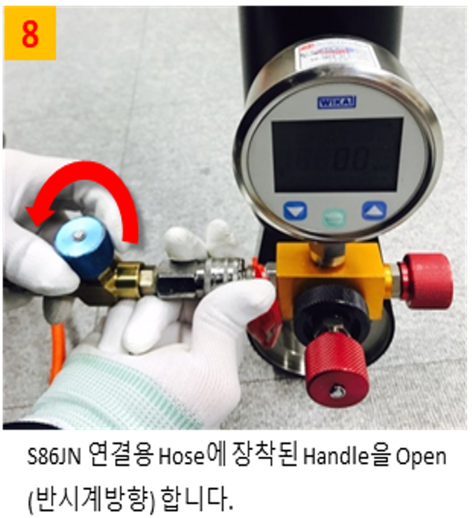
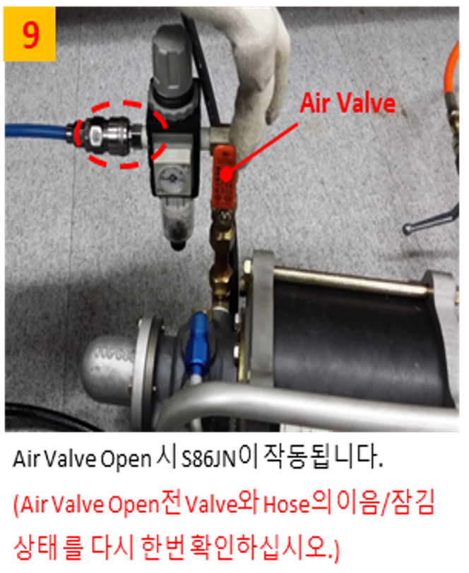
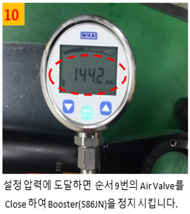
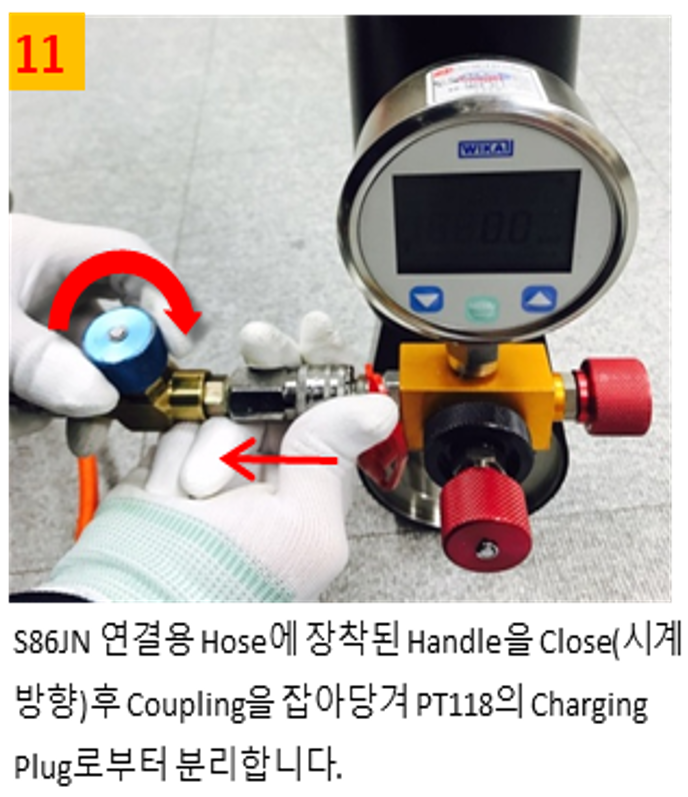
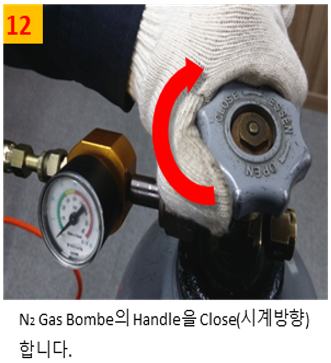
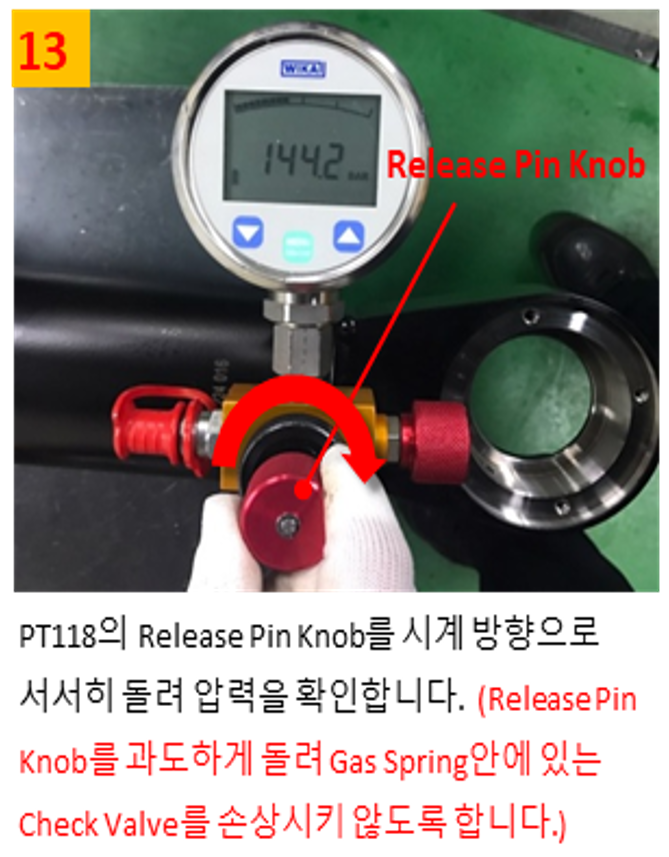
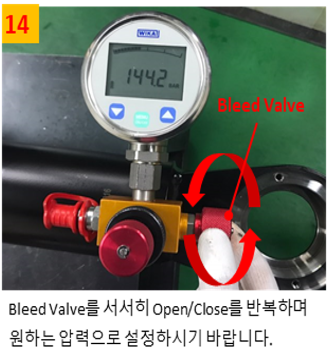
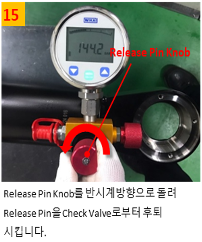
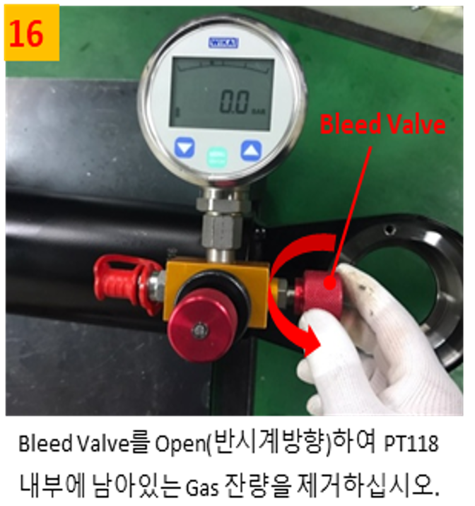
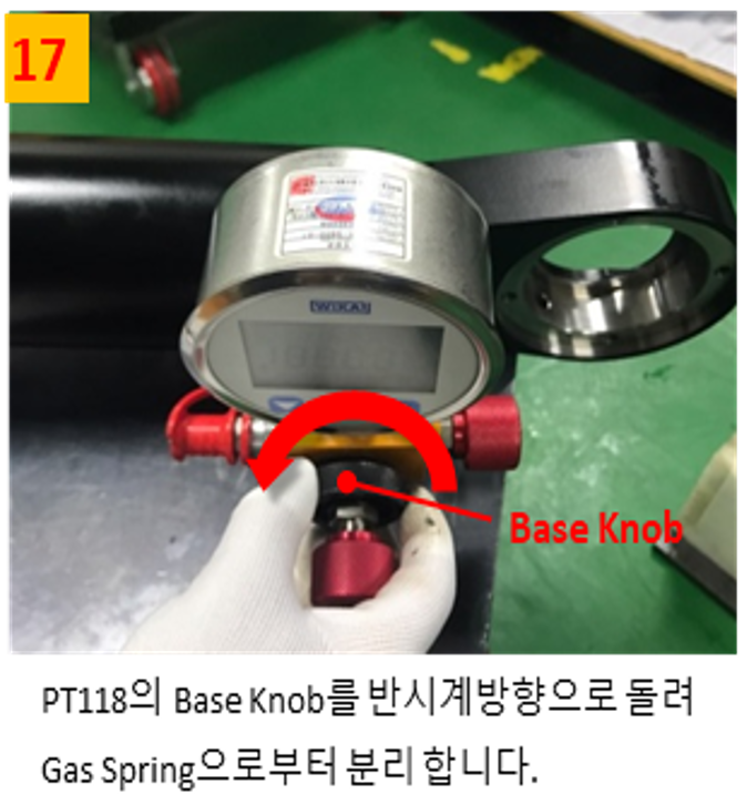
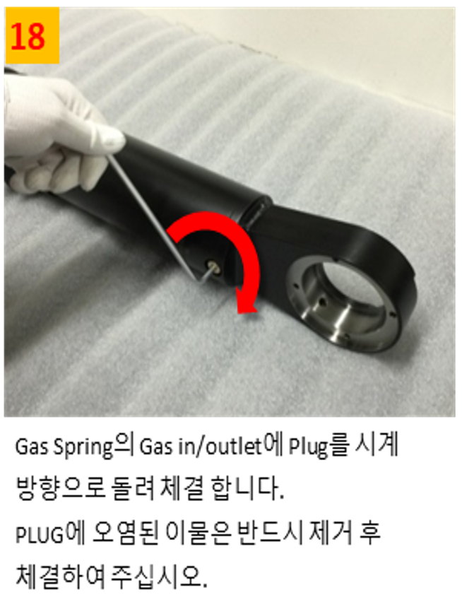
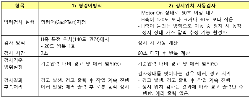
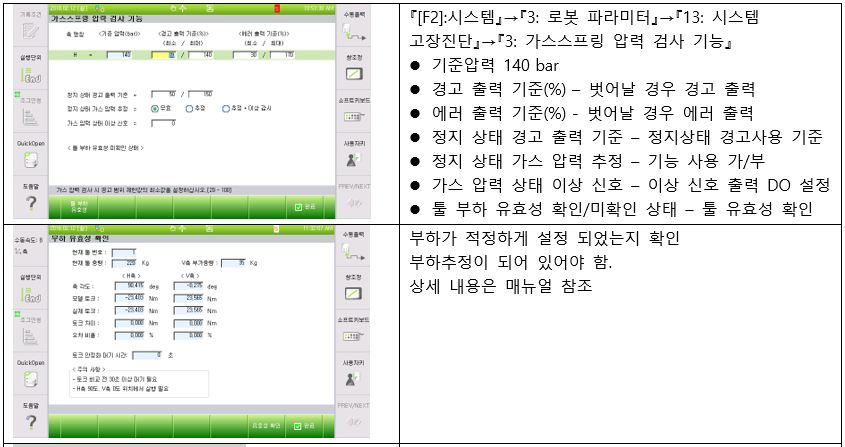
- Gas spring management (pressure inspection, injection)
- Gas spring maintenance (inspection)
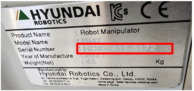
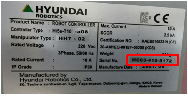
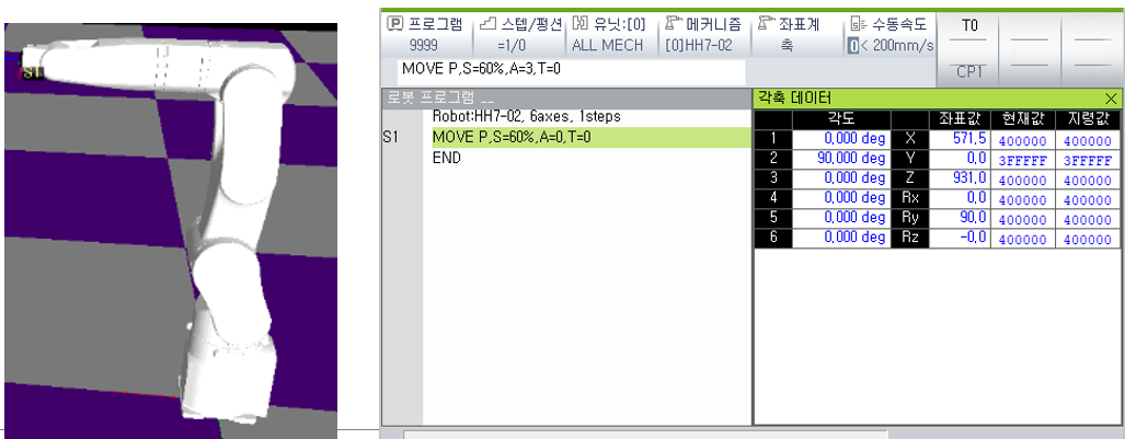
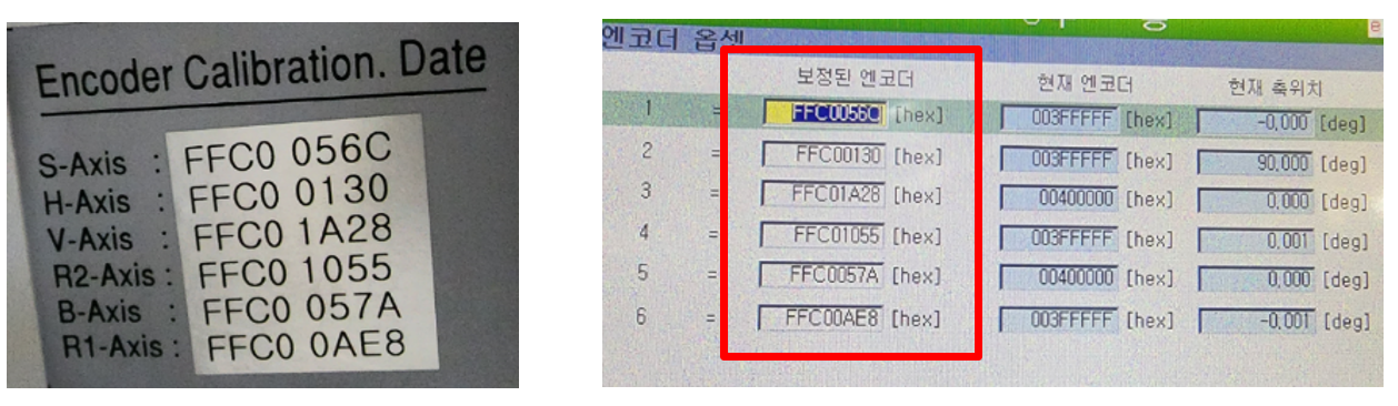
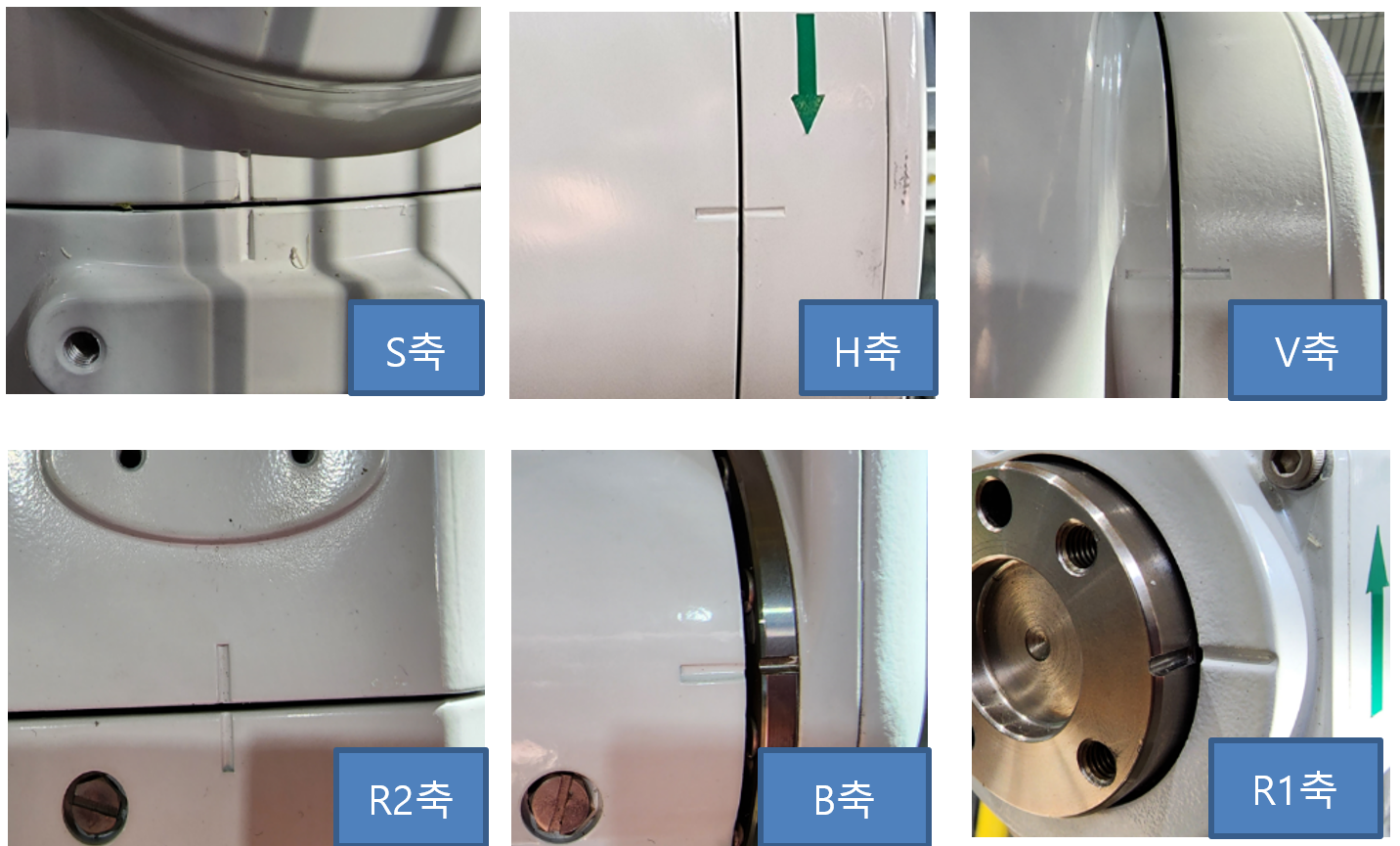
- How to check HH7 robot origin
- Gas spring management method, inspection and replacement cycle
- Notice of discontinuation of Hi3 robot parts
Index
· One min read


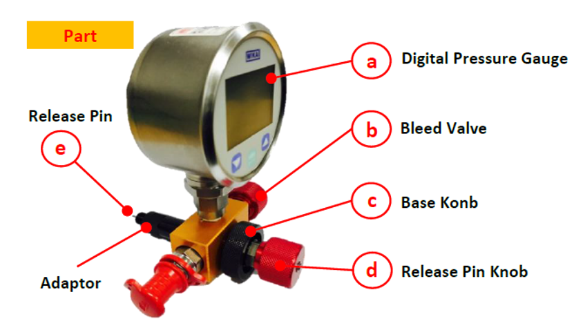
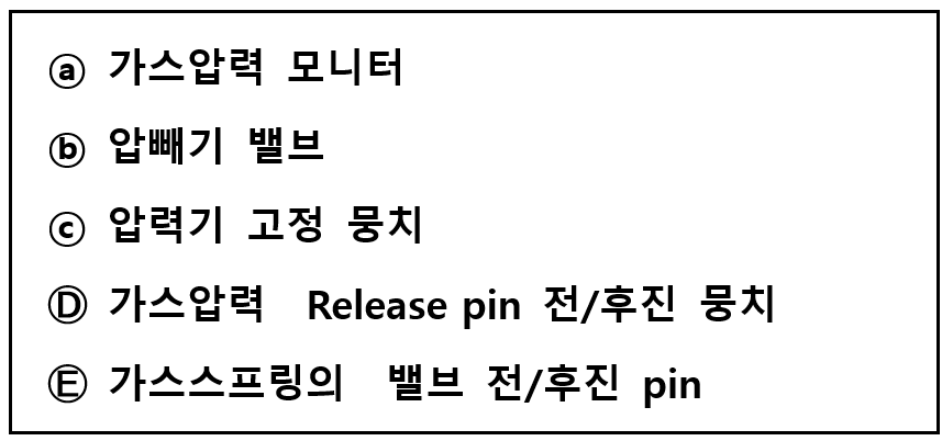
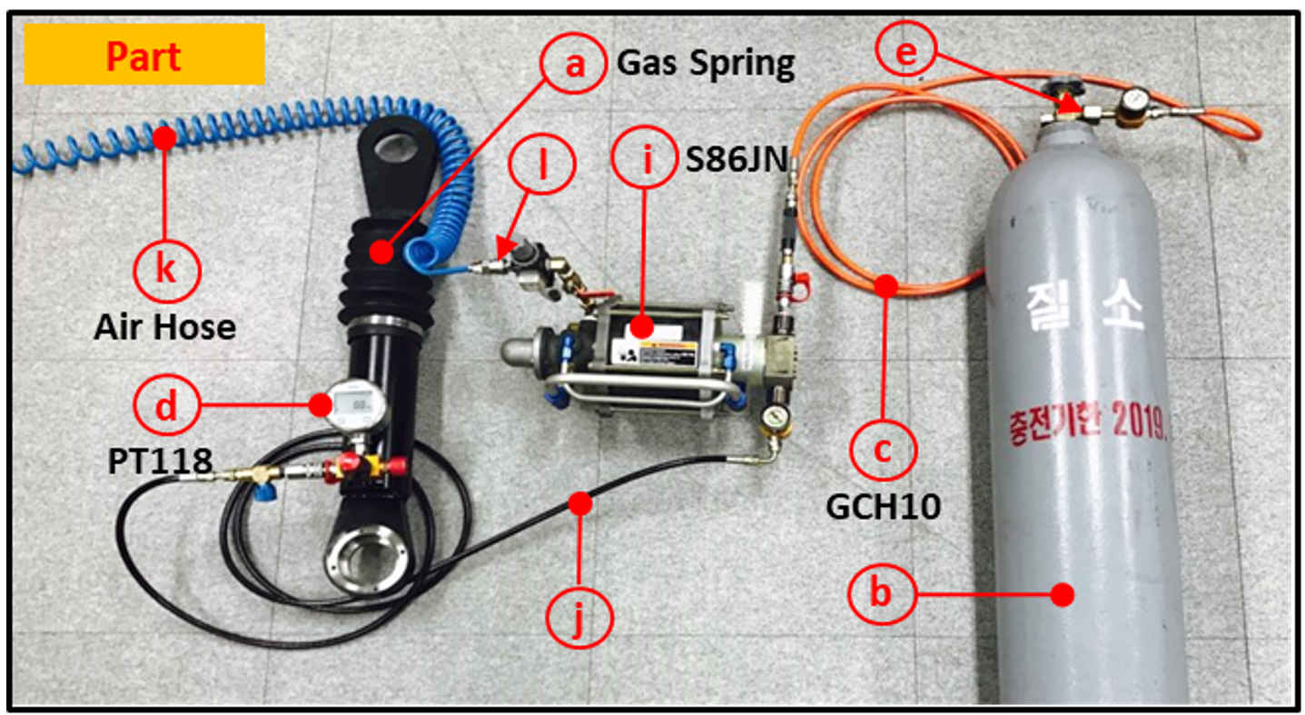
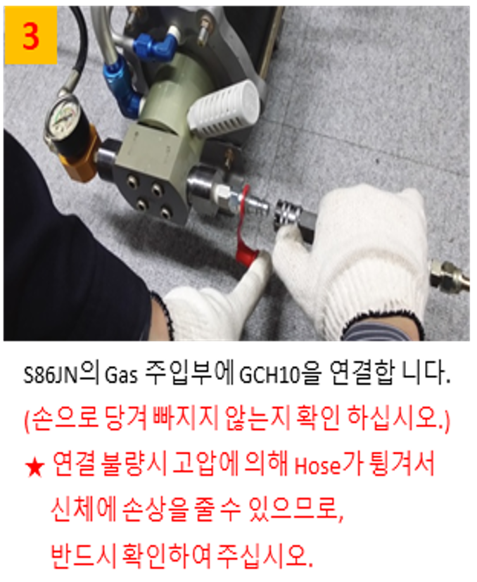
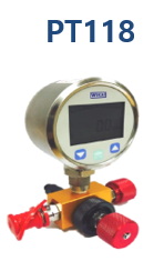
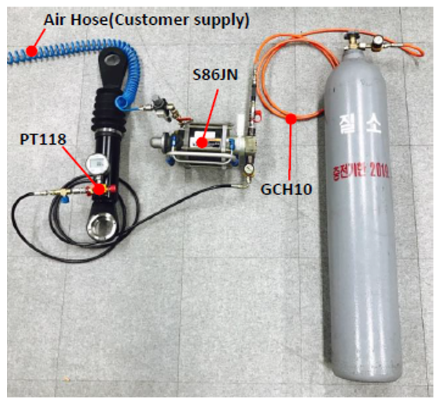 가스스프링 충진기 SET
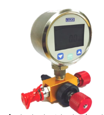 (디지탈 압력 측정기)
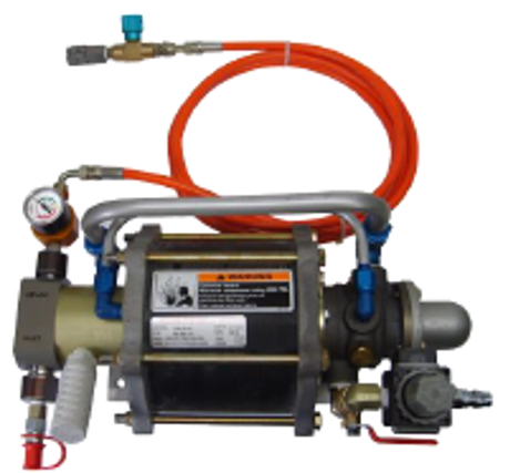 (압력 주입 부스터)